Micro Hydro Generator - Water Baby
Last update: 15 June 2006
The Water Baby micro hydro turbine is part of a hybrid 12Volt power system, providing electricity during the dark wet winter months, when the solar PV panels only produce negligible amounts of power on this shaded site. The water for this hydro system comes from four main spring areas. These springs produce a trickle of water each, but combined give enough output to run this small generator during wet spells. The geology is slate shale and clay on a steep slope. The water table is quick to react to the weather. After a prolonged dry spell, one inch of rain will make a noticeable difference within a couple of days.
The generator is an impulse type turbine, similar to a pelton, but lacks the central ridge of the buckets, and is designed for low flow situations.
I started installing the hydro system in November 2004. There were a number of teething problems with the intake, where the filters clogged up within hours. After trying out various designs, I am now able to leave it unattended for days on end, and with the installation of the next filter type I anticipate that very little attention will be necessary.
One other major problem was that the amount of water from spring #1 and #2 was not sufficient to run the generator in all but the wettest weather. This meant having to bring in more water from the spring area supplying the domestic water, a little over 150 meters along the contour. I had to get more pipe, and with the slight gradient, air locks are a major problem.
The way I got rid of the air locks was to walk along the pipe lifting it as I went along, keeping the 'bubble' at the highest point, which was driven out when I reached the end of the open pipe. This process may have to be repeated when the water level goes down and the pipe gets air into it again, however, I lowered the collection tank a little, and this additional slope may well be enough to drive out the air with the extra water pressure. This pipe is only 25mm diameter, and small diameter pipes are less susceptible to air traps when at a good slope. The main pipe is a 32mm diameter pipe and runs down a steep hill. Any air entering the pipe when the water level goes down, is quickly driven out by water following.
When I first installed the generator, I was hoping to run it off the the spring supplying the domestic water. As the pipe was already in place, this would have been a minimal installation. However, the pipe is about 300 meter long and only 15mm diameter, which created such great frictional losses, that the pressure was not enough to give any output. Never underestimate frictional losses. Good tap pressure is not necessarily enough to run this generator. As I had to run a new, larger pipe anyway, I started to look for springs nearer the site, and found a couple of good ones about 200 meter from the site.
The advantage is that the two systems don't interfere with one another, but can supplement each other when necessary. During the summer when the hydro generator will be turned off (the PV is plenty for the summer), and water levels are down, the extra source with its independent pipe can irrigate the garden and keep a pond topped up, as well as feed a moat around raised beds to deter slugs. I would have been loathe to use my precious domestic water for this purpose, as the 500 gallons are a reserve which may have to last through a drought, when the springs go down to a drip. Good permaculture in action, an important element backed up.
Over the last couple of months since getting the first Watt from the system, I have been running the laptop computer for up to 18 hours a day creating this website, which is pretty good, considering a computer uses a fair bit of power. My batteries are very low now, as the weather has been quite dry lately, and the hydro can only run a few hours a day, but as I write this, the rain is lashing down, and with more than an inch, I reckon, there will be plenty of power again in a day or two, with the batteries back to 100% state of charge.
My power situation was dire before I installed the hydro generator, with the sun dipping below the tree line again for the winter, so I wanted to get the generator running as soon as possible. Some of the setup is therefor still to be completed, mostly fixing things into place, tidying up cables, pipes, making a stand for the generator and proper housing for it, to include a dry space for the multimeter and spare nozzles and tools. Also the spring intake area needs to be covered, and filter screens installed. Those jobs will allow the system to run unattended for much longer.
I am quite pleased with the hydro generator, though I had some frustrating moments with its installation. It certainly means more light during the winter, no worries over running the computer, which allows me to do the writing work when the weather is bad, and the days are short, leaving the fine summer days to do outdoor jobs.
The measurements taken are approximate, especially the head of water. Also the turbine needs some more fine tuning, as output can be adjusted, and is probably not at its optimum at present. Tests with other machines have shown higher output with similar conditions.
Data
- Head from generator to intake - approx. 100 feet
- Distance from Intake to generator - 650 feet
- Penstock diameter - 32mm MDPE pipe, reduced to 15mm at generator
- Distance from generator to battery bank - 80 feet
- Cable from generator to battery bank - 10mm2 each
- Static pressure - 58 PSI
- Pressure gauge - 100 PSI
- System voltage - 12V
- Charge controller - Trace C35
- Typical current produced with available water - 1.9 Amp
Update
Since I bought my generator, the company has made some improvements to the stator with more efficient windings. The table shows output with the old windings, and also unsatisfactory plumbing. I have just upgraded the generator with new stators, and taken a few measurements. The results are a great improvement. With recent headline generating record rain, I am in a position again to run the generator at full output and I can test it with different nozzle sizes, and over a longer period of time.
Paul Cunningham of Energy Systems and Design has found a curious phenomenon when testing his generator; the output rises after the machine has been running for a day or so. This is what I have found also. Due to heavy leaf fall at present, I have not been able to take a second measurement on the biggest nozzle, as the partially blocked flow decreased the available water, and I had to change to a smaller nozzle on the first day. The generator has now been running two days with the smaller nozzle. The table does not show Voltage, an oversight, and unfortunately does not allow the calculation of Watts, but the relative gain can still be seen.
I have been advised, that the rather long run of 15mm pipe near the nozzle would reduce the flow somewhat. Next upgrade is larger fittings. I will test the generator first with the new stators/present plumbing and wiring, then new plumbing, then bring the generator closer to the house which will eliminating about 80 feet of pipe which runs on the flat, leaving the cable at full length, then shorten cable to see if and how much improvement any of those changes make. So here the first figures. The increased PSI may be due to continuous running purging the air in the pipe.
Nozzle no. 8
3.3 Amps
Nozzle no. 7
day one - 3 Amps
day two - 3.2 Amps at 14.2 Volt and 46 PSI
Measurements taken with original generator and system:
| Nozzle # | Nozzle size | US Gal/min | PSI | Amps |
|---|---|---|---|---|
| 4 | 1/8" | 3 | 55 | -- |
| 5 | 5/32" | 4.5 | 52 | 0.9 |
| 6 | 3/16" | 6 | 48 | 1.9 |
| 7 | 7/32" | 9 | 42 | 2.2 |
| 8 | 1/4" | 10.5 | 36 | 2.6 |
Gallery
Click thumbnails to enlarge, click popup to close

Hydro generator with temporary housing, a plastic container/bowl, and a 4" pipe sleeve and bubble wrap to protect the metal pipe section from frost damage.

The Water Baby micro hydro generator shown with the electrical junction box, the mounting frame on a temporary support, the pipe inlet with stopcock and pressure gauge. The Water Baby is available with 1-4 nozzle openings. This is a one-nozzle model, as I have very little water available.
To reduce cost without sacrificing cable thickness, I opted for earth ducting cable, and wrapped red tape around the positive cable, as there was no other colour choice.
Temporarily the generator is supported on a steel box on battens, to be replaced by a more permanent wooden stool type frame, with the four legs driven into the ground.

The pipe is removed in this shot, showing the nozzle end (usually held in with a grub screw), as well as a spare nozzle with a larger aperture. The generator is supplied with a number of nozzles, each with a different size opening, used according to how much water is available. The smallest nozzle will allow about 3 gpm through at a head of about 120+ feet, however, I have found that the smallest nozzle used with that head, produces no current at all. If the springs are gushing after a good downpour I have been able to go to the second biggest nozzle. With the new buffer tank I may be able to use the largest nozzle, when the available water is just below the quantity needed for the largest one.
The generator body is made of aluminium, and the nozzle holder/nozzle is brass, therefore there will be electrolytic corrosion where the two meet in the presence of water. You can't do anything about the water, as there will be some splash back from the turbine, but I stopped the corrosion by liberally coating the brass parts with Vaseline. When first installing the hydro I failed to do that, and after a few days of not changing the nozzle, the brass part was jammed solid in the hole, and I had to prize it out with a screw driver. With the Vaseline the corrosion has ceased.
The brass nozzle holder supplied with the generator has a standard thread for UK 15mm/1/2" compression plumbing fittings. I used a tap connector with a fibre washer, and 15mm copper pipe and ball valve. However, different brands of compression fittings can have different thread pitch, so it would be advisable to take the fitting to the plumber's merchant to try out.

The tail race is a tube I fabricated from sheet aluminium to fit the opening of the underside of the generator. The edges were riveted together and the lower edge snipped and bent in slightly to minimize splashing. Still to be done is a caulking seal around the top edge which would prevent any splash-back to seep into the timber frame. The tube is pinned to the inside edge of cross struts supporting the generator, i.e. is not directly connected to the generator.

The support frame is made of 1" x 4" rough-sawn soft wood, screwed together at the corners. Two boards are screwed across the top side of the frame, with a cutout for the 5 1/2" diameter opening on the underside of the generator. The generator is screwed to these boards, through holes provided in the corners of the housing flange. The long side boards are extended beyond the corner of the frame so that any loose cover placed over the generator would have support on the end where the electrical junction box is mounted on a vertical board.

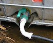
This 1000 litre tank helps to buffer the flow of water to the hydro generator. If the flow rate of the springs is just below the amount necessary for a given size nozzle, the tank will allow the larger nozzle to be used for a while, until the tank is empty. As the spring continues to deliver almost as much as is passing through the nozzle, the water level in the tank is only going down very slowly. The difference in electrical current between using one nozzle size and the next is more than is lost by having to close off the generator briefly to fill up the tank (less than an hour at 4 gpm). This is especially critical when the flow is just not enough for the smallest usable nozzle. It means being able to run the hydro maybe 20 hours a day, instead of not at all.
The blue pipe is the overflow from the spring which supplies my household water, plus another spring in the vicinity. The white pipe delivers water from two further springs.
The tank was free from a local cheese factory. These tanks hold liquid food additives (rennet and food colouring in this case - there is a second tank further up) and may be available from other types of food precessing plants. They come on a palette base, and must be used with the supporting cage, as they are a bit too flimsy on their own and buckle (tried!). Taken apart for handling, the parts are easy enough to manoeuvre, even by one person. I managed to get all parts up a very steep hill on my own without difficulty.
Connecting up a 32mm pipe to the tank without cutting open the top to crawl inside to screw on the lock ring of a tank connector needed a little trickery and compromise. The tank outlet has a screw-top lid with a removable center to be able to attach a short flanged pipe (the flange is held by the edge of the lid). The tank connector would have been too bulky in the lid, and would prevent the lid from being screwed onto the tank outlet. I bought a waste pipe 40mm/32mm reducer compression fitting, sawed off the 40mm end just above the point where it reduces, leaving a flange which fitted into the lid ring (with a sealing washer). Into the 32mm end I fitted a flexible connector, as the outlet was facing a big tree. The compression waste fitting just about fits the 32mm alcathene pipe. A push-fit connector is too loose. You would think 32mm is 32mm, but in plumbing that does not seem to hold true, just as 40mm waste pipes are not compatible between different brands. After cutting off the 40mm end of the coupler, I discovered the a 40mm Osma brand waste pipe fits snuggly into the flanged pipe supplied with the tank (after cutting off the curved spout end). If you have wast pipe off-cuts it would be a cheaper and neater option than the reducer.
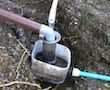
This silt trap is also the collection point for two springs (#1 on diagram - the thick pipe - the 'stream', and #2 through the small pipe). The s/s filter is a strainer from a catering tea urn. Any silt, floating or suspended debris is retained in the strainer. Any smaller, heavy particle (fine silt/clay particles) will further settle out in the outer tank. This works fairly well, but does require occasional emptying. One of the springs has another filtration system at source.

There are a number of small springs along the contour line (#2 on diagram). I chiseled a little channel along this line, slightly sloping down, and embedded a pipe into some earth at the end. This was expedient at the time, as my solar panels were producing very little electricity, but the open channel means a lot of silt and debris gets washed into the intake container, especially after a down pour. When the spring dry up, which they do after several weeks of no rain, I will cement the bottom of the channel, run a perforated pipe through it, and cover it over with geo textile, also cement the pipe into a small dam.

The source of this water is on my neighbour's land, so the intake is at the bottom of a steep little stream (#1 on diagram). The pipe is cemented into a small dam. When building the dam, I first built a temporary one with clay in front of the cemented one, so the water did not wash away the wet cement before it set.

Due to the steep open channel leading to this intake (#1), silt and debris is a problem. Here the pipe feeds into a container within the outer container. The inner one traps the heavier grit and silt, then the water overflows into the outer one. The edge of the inner container has a series of vertical cuts to form a comb type edge to filter out any floating and suspended particles. This works fairly well, but still requires periodic removal of silt/debris from trap. The next experiment will be a DIY version of an aqua sheer or coanda intake filter, which filters the water before it enters the collection tank. It is a grill made of closely spaced wires set at an angle. The water runs over the top and drops into the intake area, whilst debris is washed down the sloping wire to be dumped outside the intake container.

This spring also supplies domestic water, which is first stored in a 500 gallon tank a few feet below. When the tank is full, the pipe from the spring is removed from the tank and fed to the hydro system via another intake, spring #2 nearby. Without a washing machine and flush toilet, the 500 gallons last a fair time, and in the summer the reserve has taken me through all dry spells so far. When the hydro generator is needed most in the winter, the water is usually plentiful, and when the water in the tank is nearing the bottom, it only takes a few hours to fill it again, leaving the main spring flow for the hydro the rest of the time.

This is a filter which did not work. It was placed over the pipe outlet hole and is made of woven s/s wire. The debris gets sucked into the screen where the intricate surface traps everything. At times the whole filter was caked up with the kind of sludge seen at the top of the filter in this photograph. A better solution would be a piece of capped pipe with numerous small holes drilled into it, and the incoming water allowed to wash over the filter to rinse the debris off. The smoother surface would allow this.

This was another reasonably successful filter experiment. A piece of 40mm waste pipe with numerous small holes drilled into the side is inserted into a waste pipe tank connector, which is attached to the bucket inside-out. The pipe is not quite as high as the rim of the bucket. The water enters the bucket around the side, silt is deposited in the bucket and the water starts pouring through the holes into the central pipe, and down into the intake container below, preventing floating and suspended debris from entering. As the silt level rises, and holes get clogged up, the water can still escape over the top, and what little debris finds its way out will be caught by the next filter placed at the outlet of the next tank. Although it still requires emptying it needs relatively little attention.
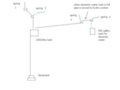
Hydro diagram
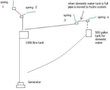
Hydro diagram, new pipe runs
Spring intake diagram
Payback period
The payback period is the length of the life of the system. What I mean by that is that you are being payed back every day with the benefit of light, music, the use of your computer, and whatever else you use electricity for. Oh, you meant cost? What is the payback period on your car, a bottle of wine, your TV, chocolate, a vacation......? If you can raise the money to pay for it without going short on necessities, you can afford it.
Related Articles

Free creativity guide to help you solve problems and design anything.

If you also want to design a solar system, you can use the moon!
External Links
microhydropower.com
makers of the Water Baby and Watter Buddy (also sell direct)
altenergystore.com
distributor of hydro generators, incl. the Water Baby, also shows pictures of inside of generator. Warning, slow loading page
norrisscreen.com (internet archive link)
for inspiration for intake screens, page link shows large scale application
wildwaterpower.com
an interesting overshot wheel
www.kimberconsulting.com
Low-Power Computing for Renewable Energy Environments
Linux and Windows Consulting and Software Program Management
off-grid.net
off-grid forum/blog